Design and calculation of power transmission for 30m high pole light panel lifting system
based on the relevant formulas and concepts of mechanics, rationally give fixed pulleys, moving pulleys, gears, axles, reducers, motors The design and calculation method of the high pole light light panel lifting system, in order to have a domestic high pole lighting technology, The conception and design of the light panel and its lifting system provide a positive effect.
1. Method of lifting the lamp panel
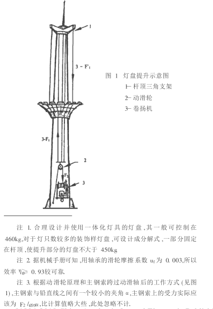
As shown in Fig. 1, three sets of steel cables are used to pass three sets of fixed pulley blocks fixed on the pole top bracket (two sets of fixed pulleys in each group). It comes down to the lifting iron plate, and one end of the main cable is fastened to the inner wall of the pole of the pole. The other end passes through the movable pulley below the lifting iron plate and is wound on the axle of the hoisting unit.

2, power transmission Design calculation
Set: The maximum weight of the lamp panel is 460kg 2. 1 The force on the three steel cables is F1 : F1 = ( 460 ÷ 3) / ( 0. 93 × 0. 93) × 9. 8 = 1 737N 2.3 The main steel cable has a diameter of 7. 7mm, a cross-sectional area of 22.37mm2, a tensile strength of 155kg / mm2, (ie 1 519N /mm2), and can withstand a maximum tensile force of 33 908N. The lifting force F 2 =2 802N. The safety factor in use β= 33908/2802= 12. 1> 8. Fully in line with the relevant national regulations. 2.4 The main structure and key dimensions of the winch. The hoisting unit has an axle diameter of 0 = 110 mm and can be wound around the length of the main cable L = 215 mm. 30m high pole light, the maximum stroke of the light panel rising or falling is 28m. The total length of the coiled part of the main cable on the axle, that is, the length of the main cable moving across the moving pulley S = 56m. According to calculation: 56m main steel cable needs to be arranged on the axle. When winding the first layer, the mechanical calculation diameter of the axle plus cable is O'0 = 110+ 7. 7= 117. 7mm; when the sixth layer is wound, the mechanical calculation diameter O′′ 0 after the axle is added with the cable is 190mm In these two cases, the minimum and maximum torques for the axles are M and M: Note 4. The 4P and 940r/min motors used here are because the motor is slow. The speed and the torque of the motor and the slow motor of the same power are larger. M Small=F2 ′ 0 /2= 2 802× 0. 118/2= 165. 3Nm ( ' 0 = 117. 7mm 0. 118m) M large = F 2 "0" 0 /2 = 2 802 × 0. 19/2 = 266. 2Nm 2.5 The axle of the hoist is coaxial with the large gear Heart combination. The indexing circle diameter of the large gear 1 = 280mm, the number of teeth is 70; the pinion gear that is connected to the large gear (assembled on the output shaft of the reducer) has a diameter of 2 = 192 mm and a number of teeth of 48. Both transmission gears have a modulus of four. The transfer efficiency between the gears η 2 = 0.95. 2.6 Due to the concentric combination of the large gear and the axle, the torque that must be paid on the circumference of the large gear is equal to M small or M large. Set the maximum force on the circumference of the large gear indexing to be F 3 : F3 = M large / 12 = 266. 2 / 0. 282 = 1 901. 4N; 2.7 pinion gears connected with large gears The force that the pinion must pay is F 4 , and the torque to be paid is M:F4= F3/η2 = 1 901. 4/0. 95= 2 001. 5N;M= F 4 2 /2= 2 001 5× 0. 192 /2= 192. 1Nm 2.8When the W PA80 reducer is used, its input speed is 800r / min, the output torque is 211Nm, the reduction ratio is 62: 1, because 211Nm> ; M (192. 1Nm), in line with demand.


