How to design a communication tower with long cantilever monitor bar
At present, the construction of urban communication base stations is generally difficult to locate, and collaborative construction with urban infrastructure can solve the problem of site selection and speeding up station construction. Based on the traditional base station design, this paper proposes a communication tower with a long cantilever monitoring pole, which not only satisfies the communication tower. The requirements, as well as the road monitoring function, provide new ideas for the construction of base stations. In this paper, the structural rationality and feasibility of such communication towers are analyzed through calculation and simulation, aiming to provide reference for the construction of municipal integrated base stations.
1 Introduction
The location and construction of urban communication base stations are becoming more and more difficult, and various types of poles are everywhere, which affects the environment. The established communication base stations are often not approved by the city planning. With the expansion of the urban area, there are problems such as the relocation and demolition of the base stations. Communication base stations, road monitoring poles, and street light poles are all indispensable and widely distributed in urban construction. If the planning and construction of new base stations and the coordination of urban infrastructure are designed to achieve resource sharing, it can be better. Solving the problem that the base station is difficult to locate and the city has more poles can also greatly reduce the unstable factors such as the relocation of the base station. The construction of municipal integrated base stations to realize the joint construction and sharing of urban infrastructure will not only accelerate the pace of the city's move to smart cities [1], but also reduce government investment and save land resources to a certain extent.
At present, the construction of communication base stations meets the network coverage requirements of operators while also meeting the functional requirements of construction scenarios, such as landscape modeling, street lighting, and monitoring. At present, long-cantilever monitoring rods for road monitoring are used to suspend carrier antennas. Such monitors are designed in a T-shaped or Г-shaped shape, and the height of the poles does not meet the requirements for antenna hanging height. The long cantilever monitoring rod has a long cross arm and more hanging equipment on it. Generally, a thicker pole and a larger foundation are required to satisfy the anti-overturning design of the entire structure. This paper proposes the joint design of the long cantilever monitoring rod and the communication tower, constructs the communication tower in the construction position of the monitoring rod, and uses the communication tower and its foundation to meet the bearing capacity and anti-overturning requirements of the monitoring arm.
2 Structure and design of communication tower with long cantilever monitoring rod
2.1 Design ideas
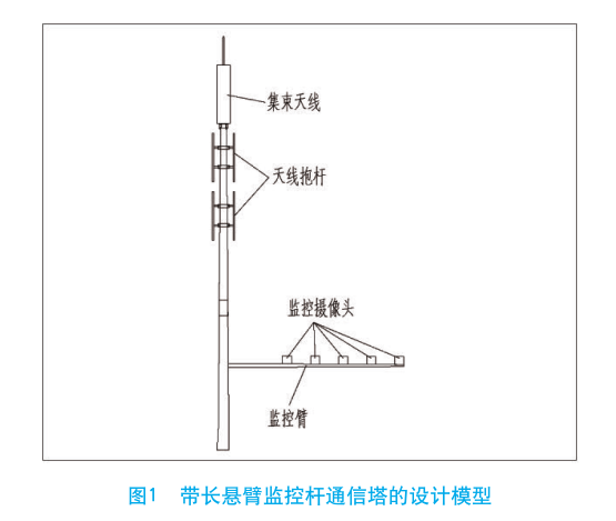
Monitoring arm of road monitoring rod, generally 4 to 12 m long, 6.5 to 7 m high, mainly equipped with monitoring equipment and road signs. The design of the monitoring arm can be determined according to the width of the monitored road. The load is determined according to the size and weight of the equipment to be installed. This article only considers the monitoring equipment installed on the monitoring arm. The height of the communication tower is determined according to the height of the antenna, and the appropriate tower type can be selected according to the surrounding environment. The load is mainly the wind load of the antenna equipment and the tower body, and the wind load is the calculated control load. The monitoring arm transmits the load to the tower through the flange connection node. The design model is shown in Figure 1.

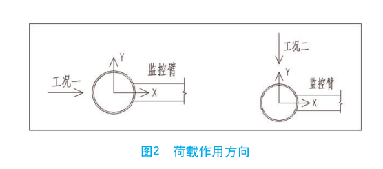
The structural design needs to meet the relevant technical requirements, and the top displacement is 1/40 tower height. The deflection limit of the monitoring arm must meet the requirements of the equipment installed on it. Due to the gravity load, the monitoring arm has a downward initial deflection, and the longer the cross arm, the greater the vertical displacement of the rod end. Therefore, the pre-arching of the monitoring arm is required from the joint node. It can be determined based on the length of the cross arm and the weight of the monitoring arm mounting device. Both the communication tower and the monitoring arm adopt a variable cross section cantilever beam model. Since the tower body and the monitoring arm are variable-section members, they are divided into equal-section members with different pipe diameters during modeling. The length of each segment is not more than 3 m. The diameter and wall thickness of each segment are used to define the model. Each section of the component is fixed by a rigid constraint at the bottom of the tower. The joint between the cross arm and the tower body is just connected, and the self-weight and wind load of the antenna, monitoring equipment, lightning rod, etc. are applied to the structure in the form of node concentrated force. The tower body and the monitoring arm are calculated according to the rough circle, and the figure coefficient is 0.9 [2]. The wind load is applied to the structure by the rod load. The cross section of the communication tower adopts a regular dodecagon shape, and the cross section of the monitoring arm adopts a regular octagon shape. Under the action of wind load or earthquake, there are two working conditions for the most unfavorable direction of the structure, as shown in Figure 2.

The control load combinations for both conditions are 1.2 dead load +1.4 wind load.
2.2 Model calculation
Take the communication tower of 0.45 wind pressure 20 m high long cantilever monitor rod as an example. Consider setting a bunch antenna at the top of the tower, and set the tower 2 layers. 6 secondary antennas. The windward area of the cluster antenna is 1.8 m 2 , the windward area of each of the plate antennas is 0.6 m 2 , and the windward area of each RRu is 0.2 m 2 . A 9 m long monitoring arm is set at 7 m from the ground, and two monitoring devices are placed on each node at intervals of 1 m to approximate the load. Each unit has a windward area of 0.1 m 2 and a weight of 0.1 kN, taking into account the load of six nodes. The structural design has a service life of 50 years, the ground roughness is Class B [3], the seismic fortification intensity is 8 degrees, and the structural material is Q345 steel.
2.3 Comparative analysis of calculation results
The communication tower calculation needs to meet the two indicators of tower strength and tower top displacement, and calculate the X direction wind direction (condition 1) and the Y direction wind direction ( Working condition 2)
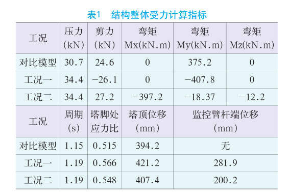
The parameters of the tower tower reaction force, the top displacement and the natural vibration period are used, and the single-tube tower model without the monitoring arm is used as the comparison model, and the calculation result is
>is shown in Table 1.

Two conditions from structural stress The calculation results show that under the X-direction wind load (condition 1), the wind load on the upper structure of the communication tower and the wind load effect of the monitoring arm are superimposed. At this time, the tower foot reaction force, the tower top displacement and the monitoring arm end The displacement is the largest, which is the most unfavorable condition for the design of the superstructure and the design of the lower foundation. The reaction force of the tower with the monitoring arm communication tower increased by 8.7% compared with the tower reaction force of the comparative communication tower model. It can be obtained that the monitoring arm has less influence on the design of the anchor bolt and the foundation of the tower, and the higher the communication tower, the smaller the load ratio of the monitoring arm, and vice versa.
3 Design and Analysis of Connection Nodes
The design of the flange of the monitoring arm can be based on the design method of the single-tube tower flange. The flange bolt connection calculation can be based on the high-strength bolt group. The calculation method of force and bending moment. For the connection node of the node on the tower is the key to ensure that the entire structure works together, and sufficient reliability is required.


